
Backstory
I live in an earthquake region and fault zone with frequent - but usually
relatively weak - earthquakes. On Tuesday, March 30, 2021, a powerful earthquake
of magnitude 4.6 occurred in the southwestern Vienna Basin. Then, on Tuesday,
April 20, 2021, another earthquake of magnitude 4.4 occurred. In the spring of
2021, the earthquakes were particularly intense to experience, because there
were additionally very many and often also noticeable quakes with very close
epicenter. The epicenter of the closest earthquake was just about 2 km from
where I live.
The so-called Vienna Basin is a geologically young tectonic basin of collapse
and sedimentary basin in the transition area between the Alps and the Pannonian
Plain. The cause of the quake activity in the southwestern Vienna Basin is the
horizontal displacement along the so-called Mur-Mürztal Fault and a prominent
deep fault near my hometown. At the fault lines of this fault system, continuous
rates of displacement cause a buildup of stress that is released by earthquakes.
The quakes in spring 2021 gave the impulse to me to deal with the very
interesting topic of measuring earthquakes, geomagnetics, infrasound and VLF
phenomena. The goal was the development of simple self-made measuring devices
without claiming professionalism.
First considerations
After an extensive literature study on the subject (see also list at the bottom),
I will on the one hand deal with the theory in a somewhat layman's way (I consider
that inevitable) and on the other hand venture a start into simple seismometers
with the very inexpensive MEMS accelerometers. If there is desire and mood,
I will later add simple magnetometers, geophones and VLF receivers to the system.
The sensors should be placed in my garden, as far as possible from roads and houses
and the data should be transmitted by radio (what else does the amateur radio
operator think) to the house for processing and storage. Photovoltaics could be
used as an energy source. All in all a very demanding hobby project for the future.
Currently the cheapest MEMS accelerometers are the MPU6050 chips or modules
with this chip. These are technically slightly outdated, but very good for a
start. There is a lot of information about them including code examples. It is
more difficult to reproduce the mechanical part of a seismometer, whose
displacement of a mass is to be measured by an earthquake. Many experiments
have to follow. But first one after the other...
MPU-6050
This interesting MEMS chip contains a gyrometer, an accelerometer
, a temperature sensor and a processor for data preprocessing.
For the seismometer, only the accelerometer and possibly the temperature sensor
are needed. A separate topic and extremely poorly documented is the programming
of the so-called Digital Motion Processor (DMP) and the FIFO
memory. Of course this accelerometer does not replace a commercial seismometer,
but even scientific articles (see references) attest the MEMS sensors quite
practicable applications as seismometers.
As always, it is necessary to carefully review the manufacturer's data sheet
and, if available, other information. As always, you can find good code and
very bad code (those people must have refrained from reading the manufacturer's
specifications) for the MPU6050 on the Internet. And in addition very valuable
information which was determined by the gurus in reverse engineering (e.g.
about the DMP of the MPU6050). The art at the beginning of this project is to
recognize the differences between good and bad code. Also, as always, I have
the ambition to understand the chip as much as possible (I really hope it
succeeds) and also to write my own code in BASCOM.
The signal path of the MPU6050 goes through the following components (without
temeratur signal): MEMS Sensor - ADC - Offset Registers - Output Registers -
DMP - FIFO.
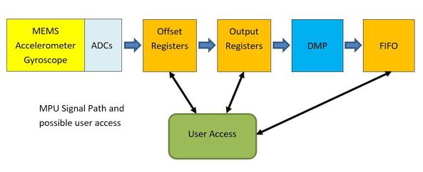
The output registers are well and sufficiently documented; the offset
registers and the FIFO rather less and a possible DMP access not at all.
The register and FIFO access is done via the I2C bus with a speed of up
to 400 kbit/s.
The breakout board has a (5V input) voltage regulator to 3V for the chip
on board (but unfortunately the 3V are not led out to the board pins). After
studying the datasheet I added a simple level shifter for the I2C bus
and for safety also for the interrupt output. Furthermore the existing two
I2C termination resistors with 2.2 kOhm were desoldered. The 2.2 kOhm are
borderline low and with a possible parallel connection of two MPU6050 in any
case much too low. For external resistors (4.7 kOhm) the 3V voltage was led out.
With the Levelshifter daughter board and a MCU test system (with ATmega644P)
now the first MPU6050 tests were run (see test firmware with Bascom). After that
the parameterization of the MPU6050 and the access to its different
registers were tested.
Interim conclusion
With the MEMS accelerometer it should now be possible to determine the difference between an initial mass and the moving ground. At this point I stop the development for the time being, because I don't have the time for this very demanding project. Further ideas would be for example a DIY fluxgate magnetometer or a DIY laser interferometer for very sensitive motion measurement. Maybe I have given someone an idea with this short article...
 Breakout Board |
 Levelshifter Print |
 Levelshifter |
 MPU Test-Board |
 Levelshifter PCB |
 Levelshifter Schem |
 MPU Signal Path |
 MPU6050 First Test |
The amount of references and links is quite very large. Therefore they were here not coded in HTML, but outsourced into a PDF. Have fun browsing. Maybe you will find one or the other interesting link or document. For convenience, I did not order the sources of information. Yes I know a mistake, but remember the whole thing is just a hobby of mine and not a scientific work.