
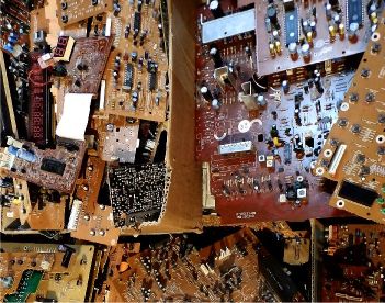
My electronic scrap boxes (see the picture above) contain many interesting old components. At the beginning of 2018 I noticed the PLL components of the old LC72xxx (Sanyo) series.
The PLL principle was of course known to me, but for example the LC72136N chip also contains an intermediate frequency counter. At the beginning I
couldn't me explain what the counter was for. A request in a relevant technical forum brought some hints, but no certainty. I was therefore very
tempted to develop a functional radio receiver (for the time being only for FM) from electronic scrap in order to be able to try out the functions in practice.
As test platform I built a microcontroller (ATmega644) with a rotary encoder and 5 buttons, a board with the LC72136N PLL and a FM front-end as well as an
intermediate frequency gain including demodulation with an old TDA1047 chip.
The software (Bascom) for controlling the LC72136N was then developed on this platform. Due to the scarce information a lot of trial and error with blood, sweat and beer
was necessary. For example, it is necessary to make an undocumented nibble swap at CCB addresses, and the readout and interpreting of the PLL output data follow a tricky
approach described hidden in several places in the LC72136N datasheet. The few sources I found on the Internet might have had difficulties with this issue as well.
In any case, the codes for the supposed solution differ.
The now working and well documented firmware can easily be used for other projects with the CCB (Sanyo Computer Control Bus) and/or LC72xxx PLL series.
And yes, the riddle with the IF counter is solved. It is used to stop a scan process at a radio station correctly. However, this method alone is not very reliable.
I would like to use the experiences with the test platform to develop a complete radio receiver later in a handicraft project. This has to be done relatively quickly, because unfortunately here in Europe more and more analogue radio transmitters are switched off...
 PLL chip |
 IF/Demod chip |
 Test setup |
 PLL Tuner schematic |
 PLL Tuner PCB |
 uC schematic |
 uC PCB |
 uC PCB |
 Control panel |
 GLCD |
 IF/Demod TDA1047 |
 10.7 MHz lim IF |
 PLL Tuner Control |