
In 2019 I wanted to start a small retro project with electronic tubes (valves).
In the tinkering box there were some so called battery tubes (1R5, DK91, DF91, 1T4, DL96 etc) for small voltage
and so I decided to build a receiver for medium wave to be able to hear the last not switched off medium wave transmitters.
The project was only planned as a weekend project, but as it happens, it was much too interesting and
also too difficult for a weekend. I didn't want to simply rebuild a circuit, I wanted to plan and calculate everything myself.
To do this, I had to dig up old documents (the tubes are from the fifties of the last century) and do a lot of research.
As a result, the RX was redesigned several times and circuit units were rebuild.
At the end there was an exciting tinkering project with a high learning factor and on 5.1.2020 I could do
a rough filter tuning for the first time and listen to AM transmitters on medium wave. This is always fascinating.
The further information should describe this receiver and show my enthusiasm for old radio technology. Maybe it is best to start the description as a kind of handicraft book with some pictures and schematic drafts. At the end then I present the complete receiver with full schematic and photos. Oh yes, "visuRX" or "Visu-RX" means nothing else than the abbreviation of "vintage superheterodyne receiver".
First considerations
After the decision for battery tubes with anode voltages up to about 90V and 1.4 V heating at 50mA,
a suitable power supply was searched for. Two old suitable line transformers were available.
The 1.4 V should not be generated by a linear regulator because of the losses, but by a switching regulator.
The receiver concept should be a superhet for about 500 - 1700 kHz. Since I had many 4.433619 MHz PAL quartzes (for IF filter)
in stock, I thought of an intermediate frequency in this range. This IF is not quite optimal, because some
whistling spots were to be expected. On the other hand, this high IF made it possible to bypass the mirror
frequency problem. The origin old receivers had an IF of only about 467 kHz. Furthermore I thought of a
self-contained VFO although the DK91 was originally developed as a pentagrid mixer with oscillator.
The construction of a stable tube VFO in the range of 4900 - 6200 kHz appealed to me especially.
As an IF filter I first imagined a so called "Kautter Quartz Filter". The input filters should be constructed
like the historical "single-range super" and should not need any further tuning by a variable capacitor.
If someone is not so familiar with the old expressions, should have a look at the references (see below).
I tried to collect many of my information sources there!
As audio amplifier a small class A amplifier with a DL96 and 1T4 tube was planned and actually I found a
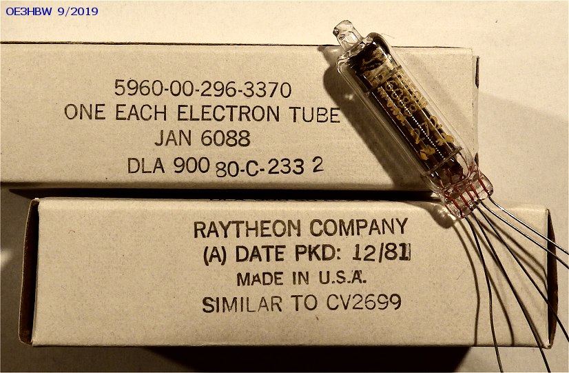
suitable output transformer for it. While searching for suitable tubes for the VFO I came across the Franklin
circuit with 2 tubes. In the tube box were some JAN6088 sub miniature tubes from US military stock.
With 1.2V heating they almost matched the 1.4V battery tubes. With this I wanted to try it.
PSU
The 1.4V for the tube heating is generated by a small line transformer from 230V mains voltage to 6V AC,
a rectifier PBL405 and further by a switching regulator with the LM2596T-Adj, a Schottky diode 31DQ06 and a
choke with 33 uH, low ESR electrolytic capacitors and followed by a ripple filter. A further common mode
choke and capacitors additionally filter the output voltage. The feedback path of the LM2596T was calculated
with Cff = 33nF, R1 = 680 Ohm and R2 = 122 Ohm. R2 is designed as a trim pot to adjust the 1.4V exactly.
The switching regulator is designed for maximum 800mA.
Another mains transformer (with 230V to about 60V AC and 7.5V AC) generates about +90V and -9V DC after
rectification (D3SB60 and KBP04). The operating voltage for the battery tubes with +90V is filtered with a
choke and two 330uF capacitors, but not regulated. The -9V for the grid bias voltage is stabilized with a
Zener diode BZX85C9V1 and filtered.
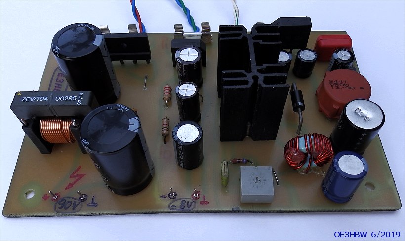
With this simple power supply the tube-RX experiments were done.
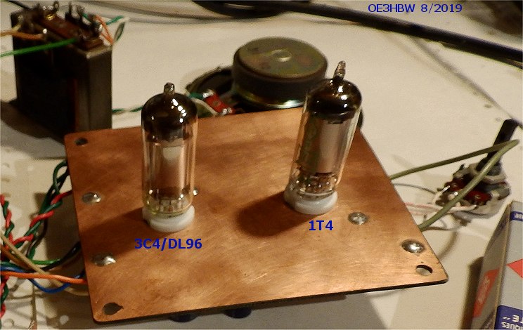
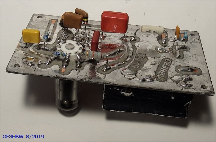
Audio Amplifier
The class-A audio amplifier has no special features. As preamplifier a 1T4 and as power amplifier a
noname 3C4 or DL96 without print is used. The gain or volume is completely sufficient. The bias voltage for
the DL96 is not generated as usual by the voltage drop of the operating voltage to a resistor in the ground line,
but is derived via a trimming potentiometer from the fixed negative PSU voltage. The transformer
(4H primary and 2.35mH secondary) from the tinkering box is loaded with an 8 Ohm loudspeaker, which results in
about 13 kOhm anode load. The heating of the DL96 is connected in parallel and draws the intended 50mA.
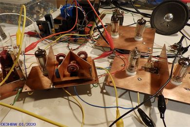
There is no mains hum to be heard even in the sloppy test setup. I now decided to build the other RX units like
the audio amplifier, namely with copper-clad printed circuit boards on both sides. The tracks should be on the
bottom and the tubes on sockets on the top. The upper side is designed as ground plane. In the case of the HF modules,
separation boards as shield can be added and the filters can be enclosed if necessary. Given the frequencies used,
this design is technically appropriate and attractive to look at.
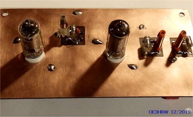
VFO
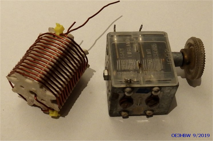
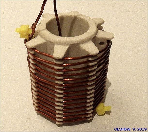
Extensive literature research and test setups were carried out for this important assembly. Finally, a Franklin
oscillator with two subminiature tubes of the type JAN6088 (pentodes) was selected. As coil (4.7 uH) 1mm CuL wire
on a ceramic body was used. The tuning is done by a variable capacitor. The used solid capacitors (old ceramic tube
capacitors and Styroflex capacitors) are carefully tuned according to the temperature behaviour (not all of them are
visible on the pictures yet).
In still open construction the deviation goes into positive after switching on, then
reverses after a few minutes and finally remains very constant (100 Hz lower than initial temperature) after 25 minutes.
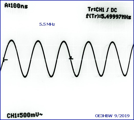
This is enough for now. The output can currently be tuned from 4.88 MHz to 6.10 MHz. The amplitude is about 1.4 Vpp at 5.5 MHz.
The power handling is low, but sufficient for the intended mixer.
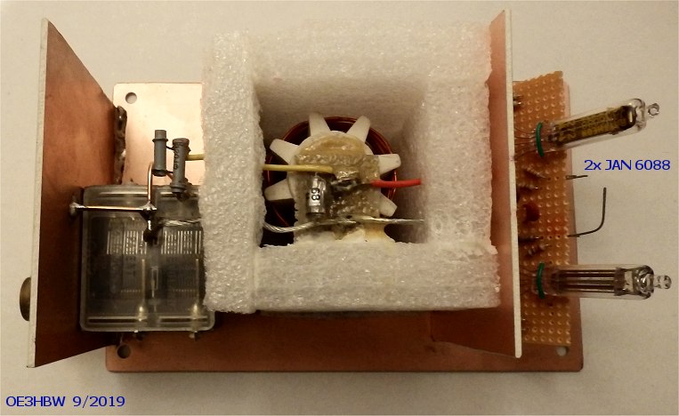
The heating of the 6088 is 1.2V at 20 mA. These are derived from the 1.4V via series resistors.
The VFO is still completely encapsulated.
Pentagrid Mixer
A DK91 with 5 grids is used as a mixer. The external oscillator signal (VFO) is fed into control grid 1 and
the HF signal into grid 3. At the anode the intermediate frequency is decoupled via a band filter (more about
this in the next point Intermediate frequency amplifier). The relatively high noise of the tube is no problem
in the medium wave range. The mixer works perfectly in this simple circuit. Nevertheless, there might be some
improvement when adjusting grids 2 and 4 or when coupling the oscillator signal in. Measurements and tests are
still being carried out.


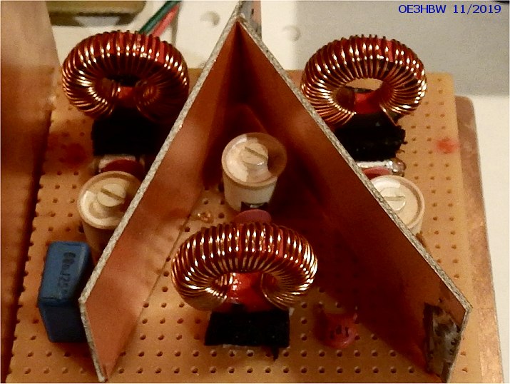
IF Amplifier with Band Filter
The intermediate frequency amplifier following the mixer and the filtering of the intermediate frequency required
the most effort. Especially the development of the band filters required many experiments.


First I thought to use quartz filters. In the tinkering box there is a belt with many PAL crystals (4.433619 MHz).
Therefore the IF was fixed to this frequency among others. Additionally I was very interested in the historical
quartz filters with variable bandwidth. As a first problem I could see that the achievable maximum bandwidth at 4.43 MHz
was too small for my purposes. Further experiments with compensated ladder filters and other topologies followed.
But the biggest problem was the quality of the crystals. These had some strong side resonances close to the nominal
frequency. Therefore I rejected the construction of quartz filters with the PAL crystals in the intermediate frequency
amplifier for the time being. Then very interesting experiments with LC circuits were made. The first filter after the mixer
is a three-circuit filter with toroidal cores. The first two circuits are inductively coupled and the following third circuit
by a capacitive high point coupling. This sequence produces a nice symmetrical edge steepness.


The first ZF amplifier has only one resonant circuit at the anode. The second amplifier couples out with a band filter
in the direction of demodulation. The total amplification is about 2000 times.
HF Amplifier
The preamplifier is used to drive the mixer correctly and to increase the sensitivity. The steepness of the battery tubes
is generally rather low. This amplifier is built with another regulated 1T4 and the signal goes to grid 3 of the mixer via a
low pass filter (1700 kHz) with 3.3 kOhm impedance.


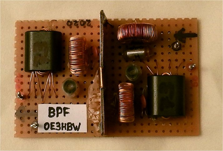
As front end a bandpass filter (500 - 1700 kHz) is coupled to grid 1 of the 1T4. The antenna connection with 50 Ohm is transformed
to 1.8 kOhm impedance.
 Schematic |
 Prototype |
The amount of references, link collection etc. is quite large. Therefore they were not coded in HTML, but outsourced into a PDF. Have fun browsing. Maybe you will find one or the other interesting document.