
Regenerative receivers (in German literature also called "Audion") are a very clever way to build receivers with a very small number of active components. However, this receiver architecture is by no means new, but on the contrary one of the first receiver circuits of the past century.
At that time active elements were very expensive and therefore one element was burdened with several tasks. This is no longer necessary and therefore the Q-multiplier (oscillator) and the demodulation of the RF signal can be realized advantageously
in separate steps. In addition, the RX front end contains an isolation amplifier that prevents the radiation of the oscillator signal via the antenna. Very important is the design of the tank coil with a high quality. For this reason, an air core coil
is used. Amplifying the audio signal would be very easy with integrated circuits. For the learning effect, however, it is good if the output stage is also equipped with discrete transistors (a Wien-Robinson-Bridge is used
as a simple test gear).
It is amazing how good reception performance can be achieved with such a very simple receiver concept (compare with HGCR 2010). In the evening hours, a large number of SW BC stations and also SSB/CW signals
from radio amateurs can be received clearly. Of course, the setting comfort is not comparable to a superhet and the selectivity is somewhat worse. However, a well tuned strong BC transmitter with excellent sound quality can then be heard. The reproducible
accurate frequency setting is difficult to achieve. Unless an additional frequency meter was installed.
Such a receiver can also be successfully recreated by beginners or with children (under expert guidance) in order not to leave the field completely
to the digital world.
My so called "Regenerix" is the product of many small development steps. Various oscillator and demodulator circuits have been tested. The path was the goal. With the shown construction phase the quite good reception of AM, SSB and CW can be adjusted
sensitively. The reception range is between 5.6 and 7.7 MHz. This includes the 49m and 41m broadcast band as well as the 40m amateur radio band. Of course, there would still be a lot to optimize!
Almost all components came out of the junkbox and can be replaced by others (unfortunately, dual gate MOSFETs are hardly produced anymore, although these components are very well suited for RF electronics hobbyists).
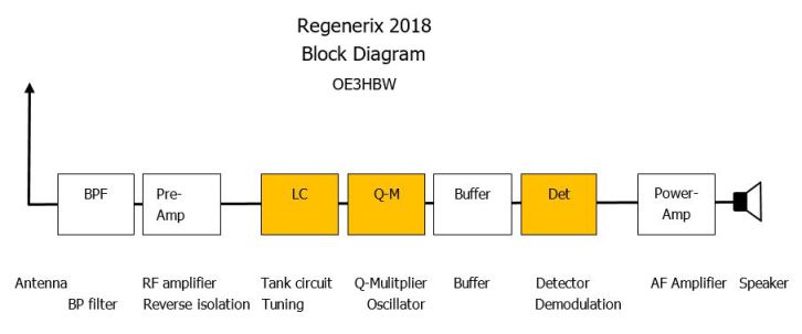
The 50 Ohm RF input after the antenna is a Band Pass Filter that attenuates strong medium wave stations followed of a preamplifier for reverse isolation. Thus the antenna is doubly isolated from the tuned circuit and the Colpitts oscillator or Seiler oscillator (as Q-mulitiplier for the LC circuit). A buffer amplifier prevent the loading the tuned circuit and oscillator. The detector is based on an "infinite impedance" design with fairly high input impedance and low output impedance that is low enough to drive the AF volume control. As an audio amplifier works a simply four transistor PA.
 RF Modul |
 RF PCB |
 AF Modul |
 AF PCB |
 Osc signal |
 BPF |
 RF Modul 1 |
 RF Modul 2 |
 RF Modul 3 |
 Tank coil |
 AF Modul |
 Test assembly |
 Regenerix |