
After I have developed many years ago a high-quality completely analog HF Receiver, I am now busy in thought with the construction of a hybrid-RX with analog front-end and digital signal processing. During preliminary studies for this project a direct conversion archtiture with passive current I/Q mixer was also a topic. At the same time a very cheap FM radio module (RRD-102 Ver 2.0 with a RDA5807M chip) flew to me from China. A toy, not a serious WBFM receiver, but somehow interesting. The RDA5807 chip should contain hybrid architecture, which I am interested in. The frequency range is specified with 50 - 115 MHz. On the internet you can find a lot of crap and no reliable information and the available RDA data sheets are incorrect and marked as "confidential". An old programmer's guide of the RDA5807SP is only available in Chinese language. Code examples for the RDA5807 can be found on the Internet - unfortunately often with little usable code or code that only uses a fraction of the supposed possibilities of the chip. So it's a lot of fun to get this little thing working despite the information gaps. Whether this will succeed?
First considerations
As hardware such a FM radio needs beside the tuner module only a MCU for control and
an AF amplifier. I will probably use my favorite MCU, the ATmega644. In addition a 128x64
LCD from the tinkering box and some buttons as well as a rotary encoder. A PSU must supply
5V for the MCU and a clean 3.3V for the RDA5807M. Because of the different operating voltages
the I2C bus needs a level-translator. Depending on the AF amplifier further operating
voltages might be necessary. If the receiver works well then can still think about a VHF
preamplifier and filter and their switching. An AF amplifier could be designed as a small
tube amplifier to spice things up a bit.
For simplicity BASCOM will be used as firmware. Programming will be difficult and exciting
because of the fragmentary documentation of the RDA5807M. The first hurdle is the correct
use of the I2C bus which is implemented in the RDA5807M. The chip handles a sequential
read/write mode and a random access read/write mode as clearly stated in the Chinese
description. Unfortunately, I am not proficient in the Chinese language. Fortunately
however DeepL, the experiments can begin.
First tests
Before I develop my own control, I use my AVR test environment to explore the peculiarities
of the RDA5807M. I solder the RDA5807M breakout board on a another
self developed board with the necessary peripherals.
A first test (First Test Code)
succeeds soon. The chip works in principle and can be addressed. The reception of a FM radio
station works fine in stereo.
Further experiments (Second Test Code) result in a fully
functional receiver of the european broadcast band (87 - 108 MHz). However, many parameters of
the RDA5807M registers documented in the existing data sheet are completely unclear or simply
wrongly documented or not designed for the hardware of the RDA5807M.
Examples:
RegH02 Bit 2 New_Method
RegH03 Bit 5 Direct Mode
RegH04 Bit 6 I2S_Enable
RegH04 Bit 0-5 GPIO1-3
RegH05 Bit 6-7 LNA_PORT_SEL
RegH06 Bit 13-14 Open_Mode
RegH06 Bit 4-7 I2S_SW_CNT
etc
Many bits are marked as "reserved". Only the registers H00, H02 - H0F are listed in the
datasheet of the RDA5807M. However, the Chinese programming guide of the RDA5807SP
contains an initialization list for 53 (sic!) registers. In short, due to the poor
documentation, many featuress are unclear.
RDA5807M Expert Mode
According to the data sheet, the RDA5807M covers a frequency range of 50 - 115 MHz.
One of my goals is to use this "RDA5807M expert mode" with the continuous tuning from
50 - 115 MHz in 1 kHz steps.
However, it is not easy to find a programming that continuously allows this big range
without changing bands. After studying the datasheet very carefully, you can find hints
for example as a footnote (page 9 in the datasheet). My experiments show that several
registers are necessary to reach this "expert mode":
In register H03, BAND [3:2] must be set to b11
In register H07, 65M_50M MODE [9] must be set to b0 (50-76 MHz)
In register H07, FREQ_MODE [0] must be set to b1
In register H08, the frequency must be written as freq_direct [0:15]
The calculation is done like this: freq_direct = (Frequency - 50000000) / 1000
The resolution of the PLL is 1 kHz and the frequency range is from 50 - 115.535 MHz.
This numerical value is stored as usual as high and low byte in register H08. In principle, the
described procedure works (Third Test Code). However,
it is unclear whether further register parameters have to be adjusted for optimal operation.
I could not find further information in any datasheet or programming guide.
Exploring the RSSI function of the RDA5807M
As with most functions, more detailed information on the RDA5807M RSSI is missing.
However, RSSI (Received Signal Strength Indicator) is an interesting feature for me, so
I experimented with it. Basically the RSSI value can be read out (Fourth Test Code)
without any problems if you wait at least 600 ms after a tuning (frequency change). After
that a stable RSSI value is obtained.
With a piece of wire (85 cm) broadcust stations with about 70 RSSI units are receivable. A
better adjustment of the antenna input (more about this later) can increase this value
by about 10 units. With this, it is also possible to work in stereo without any problems.
Since I don't have a calibrated FM measuring transmitter, I can't do a conversion to dBm
or dBuV at this time. RSSI as relative reception field strength is a ratio value. Therefore,
the value must be interpreted depending on the respective application. There are different
definitions, whereby a higher value corresponds to better reception. The RDA5805M encodes
the received field strength in the range of 0 - 127 units maximum.
Despite the quite acceptable reception sensitivity, the chip is probably only good as
an FM broadcast receiver realy useful. This especially because the DSP is in no way
parameterizable (probably only in the non-documented secret registers).
Exploring the RDS functionality of the RDA5807M
There is no official information about the RDS functionality of the RDA5807M.
The documented registers only allow a few settings and some RDS information is
missing from the readable registers. But the biggest shortcoming is the unknown
correct flow control with RDSready, RDSsync, FIFO and clear FIFO. To find out a
little more some tests were done.
However, the result of the tests is very modest. Up to about RSSI < 65, the RDS
functionality is not given at all or only to a limited extent. The error frequency
increases with decreasing RSSI. Well, this is not surprising. When "FIFO enable"
is activated, the RDSR and RDSS flags are set rapidly at the same time. With
"FIFO disable" and RSSI > 65 the "Sync flag" is set first and
then the "Ready flag". The ready flag then changes periodically between 1 and 0.
If the RSSI is weak, there is no difference between FIFO disable or enable. In
BLERA/BLERB the error rate is written and RDSR/RDSS are not set.
How the intended sequence of FIFO and FIFO clear, as well as RDSsync should be
controlled correctly is and remains mysterious due to the missing documentation
and could not be determined.
Despite the missing information, however, RDS data could be read out without
problems in test (Fifth Test Code).
Exploring the Seek functionality of the RDA5807M
In the old Chinese programming documents from 2008 and 2010 for the RDA5807P and
RDA5807SP there are three different possibilities of the Seek function. With the
register contents of the RDA5807M these agree only conditionally over, so that I
accomplished also for a band scan tests.
The European band scan works with the (Sixth Test Code).
Nevertheless, some register values are unclear again (for example, STCIEN, SF and
FM_READY are not required). Obviously, there would also be other possibilities of
a Seek, but the information is simply missing.
Concluding remarks on the RDA5807M firmware test series
The RDA5807M is a very inexpensive and interesting toy. For serious applications of the RDA5807M, however in my opinion, current and error-free programming manuals and data sheets are absolutely necessary. However, I did not find these over the Internet even after a long search. This is really a pity. Probably it is better for a radio tinkerer to use the well documented Si4703 chip instead of the RDA5807M. But with my tester knowledge I now dare to build a simple FM radio with the RDA5807M. An complete code for the RDA5807M can be written and the final hardware of the FM receiver can be designed.
Radio Input Circuit
The next target in radio building is now the RF input circuit of the RDA5807M. The datasheet does not reveal any input impedance. After some tests and measurements the antenna unit was built.
MCU ATmega644 Control Board
The next target is now the adaptation of the MCU with the
MCU with the necessary periphery to the requirements of the
receiver. An ATmega644 clocked with 18.3420 MHz is used as MCU. A PCB is already available from
other projects. A graphic display with 128x64 pixels like it was used before should be
sufficient. In addition a keypad with 5 keys and a rotary encoder to detect the direction
of rotation and with another key. A buzzer is used to generate short beeps and 3 LEDs
indicate certain states. All the components are mounted on a base plate which is
fitted into the wooden front of the receiver. For the test of this
control board a simple (test firmware) was written.
Future requirements such as a combined FM / AM receiver (for example with Si4735) were
also taken into account.
If someone wants to do own experiments with the RDA5807M or wants to build a simple FM radio
without own firmware development, he can use my firmware code in
version 0.9 as starting point. Here all necessary functionality is already present and
the step to a version 1.0 is only very small.
Audio Amplifier
And now a little bit of hardware: It's about the audio amplifier for two channels.
A solid state chip would be easy, but it's fun to mix old and new, that means a tube
(valve) amplifier (see test schematic) has to be developed.
First I thought about low voltage tubes, but then the composite tube ECL86 came into
the shortlist. Since the ECL86 is already outrageously expensive, I used the inexpensive
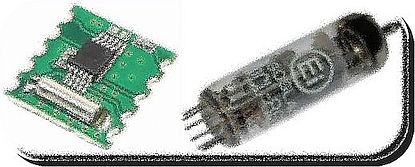
PCL86, which differs only in the heating data (300 mA series heater). The PCL86 tube (see photo)
consists of an end pentode and a triode as driver in a glass bulb. In technical jargon, I
connected the tube as a single ended (SE) amplifier. The power is about 3 W sinus. As audio
transformer I did not use an expensive high quality transformer, but inexpensive offers (H1760C).
The power supply is not stabilized, but the heater is a DC heater.
Of course, this is not a high-end hi-fi amplifier. On the other hand, the amplifier and
the corresponding power supply were carefully planned. The circuit is by no means an
unreflected replica, but calculated with regard to the data sheets of the tube and the
available components. The first test (see photo) already showed
a good sound and for a radio more than enough volume. The negative feedback was tuned for good linearization
and for the type of distortions and still sufficient volume. The amplifier is - not least
because of the PSU circuit - even during the wild test setup absolutely quiet and no hum
can be heard. A further optimization of some components may bring a tad better distortions H2, H3 distribution.
After the calculations, tests and experiments, a PCB was developed and two channels were built.
Really pretty the little stereo amplifier (see photo from one channel).
For possible rebuilders of the amplifier and tube beginners still the obligatory warning
about the high operating voltage in the range of 300V (!). This can be deadly and requires great care!
Wooden Radio Case
This time I decided to really live out the tinkering and make a wooden case from scratch. The radio should also include small speaker boxes. I have enough wooden boards in stock and the simple wood processing is not foreign to me. Wood is a wonderful material, even if some will be surprised to use a huge case for an electronic project with a microprocessor and a tiny radio chip. The photos below show the construction of the wooden case.
 Breakout Board |
 RRD-102 Modul Pins |
 RDA5807 Schematic |
 RDA5807M Pins |
 SFMR Schema 1 |
 SFMR PCB 1 |
 RDA5807M Testboard |
 Perifery |
 Control Board Part 1 |
 Control Board Part 2 |
 MCU PCB |
 MCU Board |
 MCU Enviroment |
 Control Board Back |
 Control Board Front |
 SFMR PSU Schema |
 SFMR PSU PCB 1 |
 SFMR PSU PCB 2 |
 SFMR PSU PCB 3 |
 SFMR PSU |
 PCL86 PSU Schema |
 PCL86 PSU PCB |
 PCL86 PSU |
 PSU HT Filter |
 PLF Schema |
 Power Line Filter |
 PSU Test |
 Test Amp Schema |
 Amplifier Test 1 |
 Amplifier Test 2 |
 Amp PCB (1 channel) |
 PCB Cu-side |
 PCB Components-side |
 Amp Components |
 PCL86 Amp |
 PCL86 tube |
 Amp Schematic |
 Wooden Case |
 Wooden Case |
 Wooden Case |
 Wooden Case |
 PSU Modul |
 PSU and Amplifier |
 Front in progress |
 SFMR outdoor |
 SFMR Backside |
 SFMR electronic |
 SFMR in operation |
The published BASCOM codes for the different tests can probably be helpful for
a skilled hobbyist to understand the RDA5807M better. It should not be a problem to
follow the code. However, the test code is no help for an inexperienced user who has
never dealt with the RDA5807M registers or the I2C interface.
If someone wants to do own experiments with the RDA5807M or wants to build a simple FM radio
without own firmware development, he can use my firmware code in version 0.9 as starting
point. Here all necessary functionality is already present and the step to a full version 1.0
is only very small.
 RDA5807M First Test |
RDA5807M Second Test |
RDA5807M Third Test |
RDA5807M Fourth Test |
RDA5807M Fifth Test |
RDA5807M Sixth Test |
Control Board Test |
SFMR Version 0.9 |
The links are currently not really fully processed. Nevertheless, a lot of interesting
information is already available. Have fun browsing. Maybe you will find one or
the other interesting document.
Further literature references to the audio amplifier with tubes can be found
here here.